For completeness of information about the product and the features of its operation, electrical circuits are used. The user cannot get confused during assembly due to the introduction of alphanumeric markings in the ESKD. The designation of the relay in the diagram is subject to GOST 2.702-2011, where the elements of the device are described in detail and the values are deciphered.
- Relay protection marking
- Schematic diagrams
- Wiring diagram
- Structural diagrams
- Symbol
- Graphic markers
- Letter designation
- Designations depending on relay types
- Thermal Relay Models
- Time relay
- Current relay
- Features of the designation of electromagnetic relays on the diagrams
- Intermediate relay
- Types and designations of relay contacts
Relay protection marking
To indicate relay protection, markers of machines, devices, apparatus and the relay itself are used in the drawings. All devices are depicted in conditions without voltage in all power lines. According to the type of purpose of the relay device, three types of circuits are used.
Schematic diagrams
The basic drawing is carried out along separate lines - operating current, current, voltage, signaling. The relays are drawn on it in a dismembered form - the windings are on one part of the figure, and the contacts are on the other. There is no marking of the internal connection, terminals, and auxiliary current sources on the schematic diagram.
Complex connections are accompanied by labels indicating the functionality of individual nodes.
Wiring diagram

The marking of protection devices is made on the working diagrams intended for the assembly of panels, control or automation. All devices, clamps, connections or cables reflect the particulars of the connection.
The wiring diagram is also called executive.
Structural diagrams
Allow to highlight the general structure of relay protection. The nodes and types of mutual connections will already be designated. To mark organs and nodes, rectangles with inscriptions or special indices are used to explain the purpose of using a particular element. The structural diagram is also supplemented with conventional symbols of logical connections.
Symbol
In the electrical diagram, the relay is usually denoted by a rectangle, from the large sides of which the lines of the solenoid power terminals extend.
Graphic markers
The graphic way of depicting elements is realized by means of geometric shapes:
- contacts - similar to the contacts of switches;
- devices with contacts near the coil - dashed line connection;
- contacts in different places - a serial number next to the rectangle;
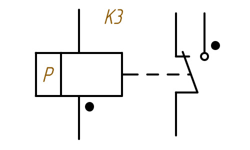
- polar relay - a rectangle with two leads and a point near the connector;

Relay contact group - fixing the switch when triggered - a bold point at a fixed contact;
- closed contacts of the relay after the voltage is removed - draw a circle on the designation of a closed or open contact;
- magnetically controlled contacts (reed switch) in the case - a circle;
- number of windings - oblique lines;
- moving contact - arrow;
- single-line conductive surface - a straight line with branch terminals;

Polarized relay - an annular or cylindrical conductive surface - a circle;
- jumpers (relay as a voltage divider) for cutting the network - a line with symbols for a detachable connection;
- switching jumper - U-shaped bracket.
Relay contacts can be signed.
Letter designation
The UGO relay is not enough for the correct reading of the circuit.In this case, the letter marking method is used. The relay code is the English letter K. For a clear understanding of what a letter on the relay diagram can mean, it is worth referring to the table.
| Letters | Decoding |
| AK | Block relay / protective complex |
| AKZ | Resistance relay kit |
| KA | Current relay |
| KAT | R. current with BNT |
| KAW | R. current with braking |
| KAZ | Current relay with filter functions |
| KB | R. lock |
| KF | R. frequency |
| KH | Indicative |
| KL | Intermediate |
| F | Fuse |
| XN | Non-removable connection |
| XT | Dismountable connection |
| KQC | Relay "on" |
| KQT | Relay "off" |
| KT | R. time |
| KSG | Thermal |
| KV | R. voltage |
| K 2.1, K 2.2, K 2.3 | Contact groups |
| XT | Terminals |
| E | Elements to which the relay is connected |
| NO | Normally open contacts |
| NC | Normally closed contacts |
| COM | Common (changeover) contacts |
| mW | Power consumption |
| mV | Sensitivity |
| Ω | Winding resistance |
| V | Voltage rating |
| mA | Rated current |
Letters can be used on a graphical diagram.
Designations depending on relay types
Depending on the type, relay devices can be indicated in the diagrams in different ways.
Thermal Relay Models
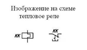
In the diagrams, the thermal relay is designated as KSG and is connected to a normally closed contact. The connection is made according to the TR system - to the output of the low-voltage motor starter.
Time relay
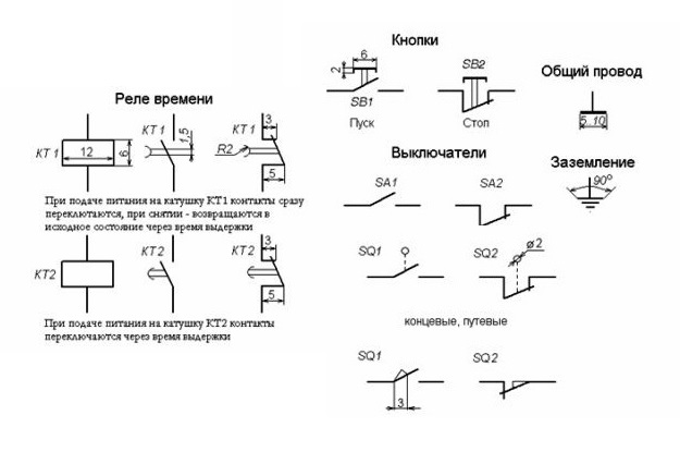
The time relay is designated as KT and works on the principle of pause with a certain action. The device can also have cyclic activity.
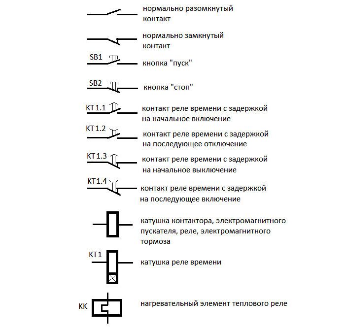
For designation of contacts working for closing in accordance with GOST 2.755-87, the following are used:
- arc down - delay after energization;
- arc down - contact triggered on return;
- two arcs in the opposite direction - delay when the control voltage is applied and removed.
Impulse make contacts are designated as follows:
- a dash at the bottom with a diagonal angular line and an arrow without a lower part - impulse closure when triggered;
- a dash at the bottom with a diagonal angular line and an arrow without a top - impulse closure on return;
- a dash at the bottom with a diagonal angular line and a normal arrow - impulse closure at the time of operation and return.
The supply voltage supplied to the time relay is marked on the diagrams as a blue graph. The direction of voltage to the devices is indicated as a gray graph. The response delay range is indicated by red arrows. The time interval is represented by the letter T.
Current relay
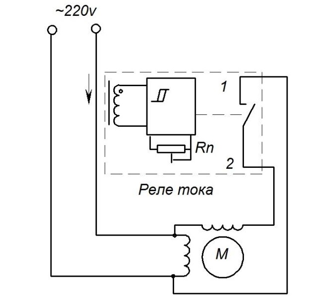
A current relay monitors current and voltage. An increase in the first parameter indicates a hardware or line problem.
On the diagrams, the device is marked as KA (the first letter is common for a relay, starter, contactor, the second is specifically for the current model). In the presence of BNT, it will be designated KAT, braking - KAW, filtration - KAZ. The coil in the drawings is depicted as a rectangle, the size of which is 12x6 mm. Contacts are designated normally open or normally closed.
The voltage winding is marked as a rectangle divided into two horizontally. The smaller one indicates the letter U, from the larger one, straight lines are directed horizontally up and down.
The current winding is indicated as a rectangle divided into two sectors in the horizontal direction. In the larger one horizontally, there are two dashes at the top and bottom. On the smaller one, the letter I is written with a larger icon (maximum current).
Features of the designation of electromagnetic relays on the diagrams
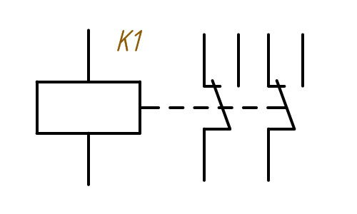
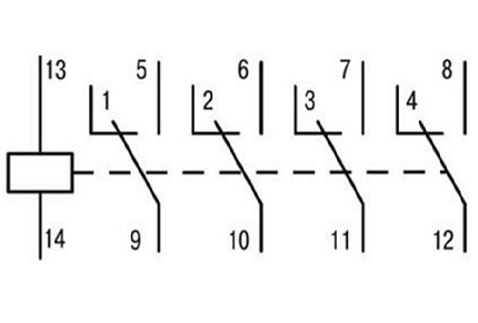
 Structurally, an electromagnetic relay is an electromagnet with one or more contact groups. Their symbols form the UGO of the device.The coil of the electromagnet is drawn as a rectangle with lead lines on both sides. Contact markers K are opposite the narrow side of the winding and are connected by a dotted line (mechanical link).
The contact conclusion can be depicted on one side, and the contacts - near the UGO switching. The binding of contacts to a specific relay is indicated in the form of ordinal numbering (K 1.1., K 1.2).
Parameters or design features can be indicated inside the rectangle. For example, in the symbol K 4 there are two oblique dashes, i.e. the relay has two windings.
Modifications with magnetically operated contacts in a sealed housing are denoted by a circle to distinguish them from standard devices. This is the reed switch symbol. The belonging of an element to a specific device is written in the form of contact letters (K) and ordinal numbers (5.1, 5.2).
The reed switch, controlled by a permanent magnet and not included in the relay protection design, has the circuit breaker coding - SF.
Intermediate relay
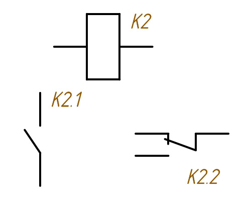
Intermediate relay devices are used to switch electrical circuits. They amplify the electrical signal, distribute electricity, and interface radio-technical elements. The symbol of the coil is a rectangle with the letter K and a serial number in the drawing.
The designation of the contacts of the intermediate relay in the diagram is carried out using a letter, but with two numbers, which are separated by a dot. The first indicates the serial number of the relay device, the second indicates the number of the contact group of this device. Contacts located near the coil are connected by hatching.
The marking of the wiring diagram and terminals is made by the manufacturer. It is applied to the cover that covers the working bodies. Contact parameters are written under the circuit - the maximum switching current. Some brands number the pins on the side of the connection.
In the diagrams, the contacts are shown in a de-energized state.
Types and designations of relay contacts
There are three types of contacts, depending on the design of the relay:
- Normally open. They open before the current is applied through the relay coil. The letter designation is НР or NO.
- Normally closed. They are in the closed position until the current flows through the relay coil. They are designated by the letters NC or NC.
- Crossover / switching / general. They are a combination of normally open or normally closed contacts. Equipped with a common switching drive. The alphabetic symbolism is COM.
Today, relays with changeover contacts are common.
It is not necessary to thoroughly study the features of the labeling. Alphanumeric characters can be written out or printed and then used for assembly. If the geometric shapes seem complex, you can always refer to the letter markings.